What makes a surface ‘perfect’?
Most people may not care about surfaces, but designers must do.
But even if people who are not really aware of the quality of a surface see and feel the difference of a bad, good or perfect surface. This is the reason why design must take care of surfaces. Especially then these surfaces will be touched or seen.
Car-designers know different kinds of surfaces:
- surfaces which never will be touched or seen by the user: class C
- surfaces which will be seen, but not often and normally not to be touched: class B
- surfaces which will be touched regulary as the product will be used: class A
These classification do not mean a special quality or kind of making, but usually class A surfaces are designed and made with much more accurateness as others. In a typical design project only 20% of the surface fall into the class A specification.
But they take 80% of the time and cost.
To make and design a class A surface you will need a capable 3D design-software. Most common software packages for this are NURBS-modelers like Alias or Catia. Polygon based modelers, like the built-in modeler in Cinema4D or Blender are not exact enough to reach the high level of curvature editing you need. I personally prefer Solidthinking Evolve, a Parasolid based modeler which doesn’t distract me with unnecessary things while working. Others may prefer Rhino or any other high class NURBS modeling software.
So what makes the difference between ordinary surfaces and classA surfaces? First of all they should appear smooth, which means there should be no visible breaks even in blended faces. But this is not the whole story, it also means that the blending should be evenly then it goes from one face to the other. This is the point things are beginning to get complex. In a traditional CAD scenario you would connect a straight line with a radius. In 2D this looks good and relatively gap-free. But this will not be the case if you transform this into 3D. You will remark a certain discontinuity in the highlights. This will unconsciously judged as poor quality by the customers. If you touch this surface and slide along you will remark a precise break there the two surfaces meet.
How can you avoid this?
First it is no good idea trying to get the whole surface in one. It will give you unusable results. In fact every complex surface is assembled by a number of discrete surface patches which form the whole form. Whilst forming you must decide which parts of the surface are main surfaces and which are dependent patch surfaces. The patches must smoothly blend to the main surface. Sounds simpler than it is.
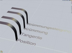
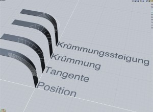
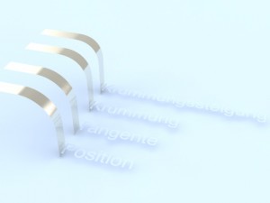
As you can see in the images above the higher the level of continuity the smoother the appearance.
First stage is positional continuity only, there is a visible gap in the highlight.
The second stage is tangent continuous and the gap is much softer.
The next and third is curvature continuous and there barely a gap.
The last shows a continuous slope of curvature and the gap disappears.
At very complex 3D scenarios it may be too costly in terms of labour to reach the maximum of continuity at any patch, so the designer must decide there super-perfect surfaces are needed and there perfect ones are sufficient.
Then it comes to organic looking forms the designer has always to make a compromise.
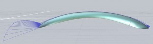
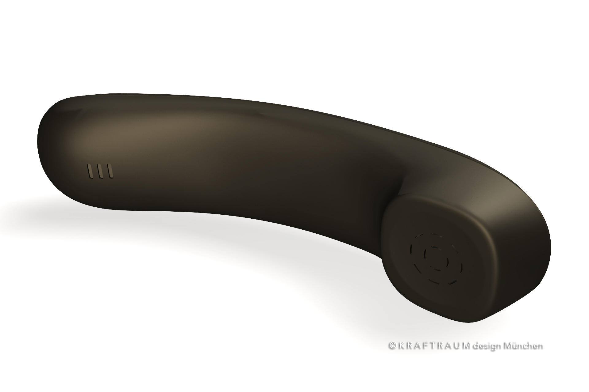
But as you see in in the sample below it is possible to get a gap free surface blending even in very complex forms which are stitched form many patch surfaces.
- CategoryAllgemein, Industrial Design